What is Blast Furnace Gas (BFG)?
Blast furnace gas is produced in a blast furnace during iron smelting process and is a mixture of carbon monoxide, carbon dioxide, nitrogen, hydrogen and methane.
The flow rate and parameters of the blast furnace gas depend on operating conditions of the furnace and can be described as follows:
– specific yield of gas from 120 to 200 m³/ m³ of the furnace volume per hour;
– excessive top gas pressure from 0,06 to 0,25 MPa;
– gas temperature before cleaning 100-350 °С;
– water vapor content in gas 20 – 100 g/m;
– blast furnace gas composition: СО – 28,7%; СО₂ – 16,5%; Н₂ – 12,1%; N₂ – 42,7%;
– combustion value 3,5 – 4 MJ/m³.
How is Blast Furnace Gas used for Power Generation?
There are 2 main application spheres of blast furnace gas:
– using excessive pressure;
– using chemical heat.
Using excessive BFG pressure.
With an increase of blast furnace gas pressure from 0.16-0.18 to 0.26-0.28 MPa (abs.) the furnace production rate increases by 5-10%, coke consumption decreases by 5%, flue-dust blowout is reduced by 50% and power generation makes 1 MW per 40-50 thousand m³/h blast furnace gas. Due to installation of TRT (top-pressure recovery turbines) it is possible to generate electricity without using fuel and compensate up to 35% of energy costs for blast-furnace air.
In addition to the economic effect installation of TRT also has an environmental effect. An environmental assessment of TRT installation can be carried out based on greenhouse gas (GHG) emissions, the source of which at ferrous metallurgy enterprises is fuel. Using blast furnace gas energy for power generation with an installed TRT leads to saving of natural gas, which would have been consumed to produce this electric power. Data on greenhouse gas emissions (in terms of CO₂ equivalent) with an installed TRT are calculated based on the amount of electricity generated and the amount of natural gas saved (presented in the table below).
| Parameter | Furnace operation mode | |||||
| Furnace volume, m³ | 1386 | 1513 | 1719 | 2000 | 2700 | 5000 |
| Annual electric energy production, mio. KW | 43,7 | 48 | 58,3 | 66,8 | 83,1 | 187,7 |
| Natural gas saved, mio. m³/year | 4,8 | 5,26 | 6,39 | 7,33 | 8,83 | 20,3 |
| Reduction of GHG emissions, thousand tons/year | 16,3 | 17,9 | 21,8 | 25 | 30,1 | 69,1 |
Using BFG chemical heat.
First of all, a part of blast furnace gas is burned in hot blast stoves to raise the temperature of air that is injected into the furnace. In modern blast furnaces the hot blast temperature rises to 1200 °C. This intensifies blast furnace smelting processes and reduces coke consumption which in its turn decreases production costs and environmental impact and the carbon footprint.
The rest of the blast furnace gas, mixed with other metallurgical gases (coke oven and converter gas) as well as natural gas, can be used by various consumers at the steelmaking enterprise, including a power plant to generate electricity.
Using blast furnace gas for power generation has both economic and environmental benefits. It makes possible to reduce consumption of electric power from external sources and thereby to avoid combustion of additional fuel for power generation.
With proper use of energy of all process gases generated a steelmaking enterprise can fully cover its power needs and even partially transfer it to external consumers, becoming a producer of electricity instead of a consumer.
An example of rational use of metallurgical gases at steelmaking enterprises is a project at PJSC “Alchevsk Iron and Steel Works” (PJSC “AMK”), which specialists of M HEAVY TECHNOLOGY took part in. It is a complex of infrastructure of a combined cycle gas turbine power plant (GTS CC) with a capacity of 303 MW for using energy potential of secondary fuel gases.
The project consisted of two construction stages. The first stage included infrastructure facilities for putting in operation block No. 1 with a capacity of 151.5 MW (supply of blast furnace and coke gases to the GTS CC). The second stage of construction included infrastructure facilities for putting in operation block No. 2 with a capacity of 151.5 MW (supply of converter gas to the GTS CC).
A mixture of fuel gases with a flow rate of 607 thousand Nm3/hour and a calorific value of 4396 kJ/Nm3 (1050 kcal/Nm3) made it possible to generate 303 MW of electricity, using two gas turbine units with a capacity of 151.5 MW each. These installations are the main equipment of the GTS CC.
It should be noted that before the gas turbine power plant was put into operation, consumption of electricity by the enterprise made 240 MW. For its own needs the GTS CC used about 14 MW of electricity per hour.
The main fuel component in the gas mixture used in the gas turbine is blast furnace gas, which was previously combusted at gas discharge devices (GSU No. 1, 2, 3). The consumption of BFG was ~ 500 thousand nm3. The pressure in gas pipelines is created due to the residual gas pressure (1200–1300 mm of water column) after BF gas cleaning and is maintained by a gas holder with a capacity of 100 thousand m3 (Fig. 1).
The entire volume of blast furnace gas, required for operation of gas turbine units, flows through a gasholder to reduce fluctuations in calorific value of gas fuel and prevent blast furnace gas stagnation and cooling below +10ºС in the gasholder in winter. After the gasholder blast furnace gas enters a special gas mixer with a pressure of 1300 mm of water column, where it is mixed with converter gas. Next, mixed gas is supplied through a gas pipeline to a gas turbine power plant.
The second important component of the gas mixture is the excess coke oven gas, produced at the coke oven batteries of PJSC “Alchevskkoks”. A coke oven gasholder is connected to this gas pipeline, which serves as a buffer tank by changes of gas flow from the coke plant and maintains its stable pressure before gas blowers.
A mixture of fuel gases with a total calorific value of 4396 kJ/m3 (BFG and CG for the first stage of construction) enters a wet-type filter after the gas mixer and then goes to a multi-section gas compressor, which is driven by a steam turbine. In the compressor the fuel gas is compressed and heated to a temperature of 450ºC and then sent to the combustion chambers of the gas turbine. Combustion air is cleaned in an air filter and supplied to an air compressor, located on the same shaft with the gas turbine, where it is compressed and sent to the combustion chambers of the gas turbine, forming a fuel-air mixture with fuel gas.
After the turbine combustion chambers, hot working gas expands in the gas turbine, where its thermal energy is converted into mechanical energy to drive an alternating current generator. After the gas turbine, exhaust gas is directed through an outlet diffuser and a tubular compressor into a waste heat boiler and then into a chimney. The heat of exhaust gases after the gas turbine is used in the waste heat boiler to produce high pressure steam (8.5MPa and 541ºC) and low pressure steam (0.79MPa and 275ºC), which is sent to the block of high and low pressure stop and control valves of a single-flow steam turbine. After passing through the stages of the steam turbine the steam enters the condenser. Steam cooling in the condenser is carried out by means of recycling water, coming from a circulation pump station. The water is cooled down in a mechanical-draft cooling tower. A condensate pump pumps the condensate into the deaerator and then sents it back to the waste heat boiler.
One of the main conditions for reliable and safe operation of the GTS CC is an uninterrupted supply of required quantity of secondary metallurgical fuel gases with required parameters (temperature, pressure, calorific value, dust content). To collect secondary fuel gases from various sources and to supply it to the GTS CC a system of gas pipelines with control and shut-off valves, gasholders and a gas booster station are used (Fig. 2).
To smooth out fluctuations, associated with changing gas output and ensure its uniform supply to a gas turbine power plant a buffer system of large-volume gasholders was used in Ukraine for the first time:
– blast furnace gas – 100 thousand m3,
– converter gas – 80 thousand m3,
– coke gas – 50 thousand m3.
A GTS CC is a modern and economical technological system that allows for the most efficient recycling of secondary blast furnace and converter production gases, as well as coke oven gas to cover power needs of the enterprise.
The use of secondary energy resources made it possible:
1. To significantly reduce the expenditures of the enterprise owners for purchasing primary energy resources and increase efficiency of their use. This, in its turn, reduced production costs by generating its own electricity and increased its domestic and foreign market competitiveness. 2. To reduce emissions of such harmful substances as CO, nitrogen, NO, including sulfur dioxide into the atmosphere due to taking out of operation a significant part of coal-fired thermal power plants facilities, which in its turn guaranteed required levels of environmental impact. The measures provided for by the project to prevent possible emergency situations made it possible to determine the degree of environmental risk and environmental safety of the facility during operation as minimal.

Fig.1. Simplified schematic diagram of the gas transportation system for supplying fuel gases to a combined cycle gas turbine power plant
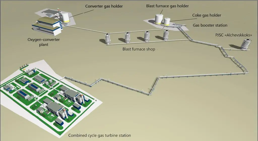
Fig. 2 Gas turbine power plant with infrastructure facilities for using blast furnace, coke and converter gas.
What for is Blast Furnace Gas used in Steelmaking and other Industries.
At many enterprises excess blast furnace gas is burned in flare stacks, although there is always a need for energy resources.
A good example is a project of our company for a new construction of mixed gas pipelines and gas booster stations No. 1 and No. 2 of the steem-gas shop at PJSC “ARCELORMITTAL KRYVYI RIH”.
As part of this project, secondary flammable gases were used as fuel, formed as a result of operation of blast furnaces and coke production:
– maximum volume of blast furnace gas – 97 596 nm³/h;
– maximum volume of coke gas – 50 724 nm³/h;
When creating mixed gas natural gas with maximum volume of 22,404 nm³/hour was used.
Three gas mixtures were prepared:
– COG-BFG mixture;
– BFG-NG mixture;
– COG-BFG-NG mixture.
For preparation and further delivery and use by consumers a gas pipeline system, gas booster stations, gas mixing stations were provided.
The consumers of mixed gas were the following production facilities:
– rolling shop;
– forging department of the foundry shop;
– iron foundry shop;
– merchant bar mills МС-250- 1, 2, 3, 4 and 5;
– blooming mill shop;
– pellet plant.Implementation of this project made it possible to significantly reduce emissions of harmful substances into the atmosphere, including CO, nitrogen and NOх, as well as reduce production costs by decreasing consumption of natural gas and other purchased energy resources.
Problems of using blast furnace gas and ways of their solving
The main challenges of using blast furnace gas are a rather low calorific value of 3.5 – 4 MJ/m³, possible presence of dust and high humidity. However, there is a number of solutions at the present time that allow us to solve these problems and to use blast furnace gas in the optimal way. These are modern gas cleaning plants, including dry-type gas purification plants with bag filters, TRTs, gas mixing and gas booster stations, which enable preparing gas mixtures with the required caloric content and parameters. Our company has extensive experience and a number of successful projects in using secondary metallurgical gases.
Have you already determined Your Challenges Using Blast Furnace Gas and are Looking for the Best Solutions? Talk to Our Engineers and Find Out How We can Assist.
Environmental Benefits and Sustainability of Using Blast Furnace Gas
The main source of CO2 emissions in iron and steel industry is blast furnace production and especially coke which is used for reduction of iron ore to iron. Coke has two main functions in blast furnace production. First and foremost it plays the role of a reducing agent in the reduction reaction of iron oxides, as well as that one of an energy source. Therefore, it is very important to reduce negative impact of blast furnace production on the environment, and one of the ways to do it is full BFG recovery, which makes blast furnace production cleaner and more attractive. Besides, the proper use of secondary energy resources reduces prime costs and makes production more reliable and independent of external resources.
Read also: Guide on Green Steel Making Process and Impact on the Industry
What is M HEAVY TECHNOLOGY Experience in Using Blast Furnace Gas
Another example of successful use of blast furnace gas is a facility, which M HEAVY TECHNOLOGY experts also designed: Recovery heat power plant for utilization of blast furnace gas at NLMK

Fig. Construction of HPP for blast furnace gas recovery.
The recovery HPP was built to recover blast furnace gas (a by-product of metallurgical production) from the NLMK network and to use it for power production and providing consumers with hot water and steam.
The raw material for it was blast furnace gas from furnace No. 7. The project allowed for increasing the level of self-sufficiency in electricity to 53%.
Its construction and commissioning made it possible to reduce the cost of the main products. The payback period of the project was about 8 years.
The recovery HPP made it possible to utilize gas in volumes of 360 thousand cubic meters per hour. At the same time, along with the generation of electricity, the thermal loads of the plant were covered by supply of industrial steam and hot water. Utilization of blast furnace gas to generate electrical and thermal power allowed the enterprise to save more than 260 thousand tons of standard fuel per year.
Of no less importance is the fact that combustion of blast furnace gas in steam generators of a HPP solves an environmental problem by preventing the blast furnace gas release into the atmosphere and reducing harmful emissions to acceptable concentrations.
BRIEF DESCRIPTION OF THE MAIN SOLUTIONS
A recovery HPP included the following complex of buildings and structures:
- main building (boiler-turbine shop, including three steam turbines ПТ-40/50-8.8/1.3 with an installed capacity of 50 MW, electric generators TTK-50-2U3-П, power boilers E-220-9.8-540ГД with steam capacity of 220 t/h for combustion of blast furnace gas together with natural gas, equipment for heating and pumping network water and auxiliary equipment);
- draft chimney (with three shafts, one for each boiler plus one standby space for the 4th shaft from the 4th boiler);
- open switchgear 110 kV (OS-110 kV);
- auxiliary switchgear (BOP-6 kV);
- main control panel
- pump station for circulating water supply;
- four-section fan cooling towers (three) for evaporative cooling of process water for steam turbine condensers and auxiliary equipment;
- pump stations for domestic and industrial storm sewerage for pumping water, collected at the HPP site, into NLMK wastewater recycling systems;
- water treatment plant with tank facilities for chemical treatment of raw water for make-up of the HPP steam power cycle;
- gas-pressure control station for natural gas supply to power boilers;
- administration and amenity building;
- a cable gallery between OS 110 kV of the HPP and OS 110 kV MSS-18; a transition bridge with a cable gallery between the main building and the main control room, a cable tunnel between the main building and the water recycling pump station;
- intra-site networks, utility lines (including technological overpasses), roads.
COST-PERFORMANCE RATIO OF THE PROJECT
- Installed electrical power in the condensing mode of operation of steam turbines, MW – 150;
- Rated electric power at maximum steam consumption from steam turbines for production and heating needs, MW – 120;
- Available annual supply of electricity, taking into account the basic operating mode of NLMK consumers and the standard frequency and duration of the main equipment of the HPP during current and major repairs (corresponds to the average annual number of operating hours of 8000 hours), kWh/year – 959.2 million;
- Rated pressure, temperature and consumption of steam, supplied for production needs of NLMK – 1.2MPa, 250°C, 120 t/hour;
- Available annual heat supply in steam for production needs of NLMK, taking into account basic operating mode of NLMK consumers, removal of the main equipment for current and major repairs and equipment reliability factors, Gcal/year – 694100;
- Maximum thermal rating for heating network water (temperature schedule – 105/700°C, minimum design temperature of outside air for heating – 27°C) for heating and ventilation of NLMK consumers, Gcal/hour – 115;
- Maximum design thermal power for heating network water for hot water supply, Gcal/hour – 9 (150 t/hour for hot water supply to consumers;
- Estimated total annual heat supply for heating, ventilation and hot water supply to NLMK consumers is 315,300 Gcal/year, incl. for hot water supply, Gcal/year – 79000;
- Essential savings of energy resources in operation of the NLMK HPP plant is due to combustion of blast furnace gas, generated as a by-product of metallurgical production process, i.e. as a secondary energy resource. Using of blast furnace gas for operation of HPP power boilers (up to 120,000 nm3/hour, for one boiler E-220-9.8-540 ГД) is equivalent to saving primary energy resources in the amount of up to 317 thousand tons of reference fuel per year.
- Land area, hectares – 9.7, building density – 32.4%;
- Reduction of harmful emissions into the atmosphere – because blast furnace gas contains 20.7% carbon monoxide (CO), and by its after burning (before construction of the HPP CC) in a flare stack it was not combusted completely and a large amount of CO was released into the atmosphere;
- Decrease in production costs of the main products, power generation and heat and hot water supply to the consumers, as well as steam provision for production needs.
Would You Like to Have Free Consultation From Our Blast Furnace Engineers?