Intro
Global trends in designing power generation facilities are aimed at enhancement of development and implementation efficiency of facilities at minimal costs.
In designing thermal power plants M HEAVY TECHNOLOGY pays special attention to reliability, safety and adaptability of solutions, taking into account market demands.
Benefits of Ordering Turnkey Power Projects of M HEAVY TECHNOLOGY
The advantage of working with our company is development of all parts of a project:
- Boiler equipment,
- Turbine unit,
- Electrical substations,
- Gas supply,
- Coal storage.
M HEAVY TECHNOLOGY also carries out thorough development of auxiliary units for efficient operation of power generation facilities:
- Water treatment,
- Equipment cooling systems,
- Process automation.
Modern tools, used by M HEAVY TECHNOLOGY, allow for forecasting specific solutions even before construction or modernization starts. It will, in turn, reduce project time limits, minimize risks and unforeseen situations at the construction site, and, most importantly, lower the overall construction budget.
Turnkey Power Plant: Features of the Building Process
Competent design and construction of turnkey power plants is a complex and multi-stage process that encompasses all phases from the conceptual idea to the final implementation of the project.
Laser scanning and modeling of existing conditions
For the reconstruction and modernization of existing power generation facilities our specialists use laser scanning, followed by BIM modeling, thereby guaranteeing high tempo and quality of work.
Based on the information received, a 3D model is developed, which is necessary both for subsequent design of all parts of the project and for carrying out calculations using computational fluid dynamics (CFD) and finite element method (FEM) methods.
Laser scanning is also used for geodetic surveying of areas during construction of new facilities.
CFD Simulations and FEM in the power plant design process
CFD (Computational Fluid Dynamics) and FEM (finite element method) play an important role in power plant design. These tools enable engineers to accurately analyze and optimize heat transfer, fluid dynamics processes and perform strength calculations.
By using these methods specialists can visualize gas and liquid flows, determine hydraulic losses, calculate cooling efficiency, analyze and optimize various elements of building structures and calculate the strength of pipelines.
All this ensures increased reliability and safety of equipment operation and makes possible to reduce costs during design and construction.
Thermal calculations
CFD modeling is used, for example, for cooling systems engineering. With its help engineers can optimize distribution of heat flows, which allows for efficient heat transfer and recovery, and helps select equipment: air-cooled heat exchangers, cooling towers, pumps.

Fig. 1. Calculation of the tuyere stock cooling, water temperature in the wall layer.
Heat transfer calculation includes, among other things:
1. Heat exchanger engineering: determination of heat transfer efficiency in various heat exchangers such as heaters, condensers and evaporators.
2. Temperature field analysis: Determination of temperature distribution (heat dissipation) of various equipment elements (Fig. 1).
3. Optimization of thermal insulation: determining the optimal thickness and location of thermal insulation to minimize heat loss.
Design aerodynamics
Aerodynamic calculations with the use of computer models in designing of such complex facilities as thermal power plants are the key to reducing losses and increasing equipment efficiency.
For example, CFD analysis is successfully used for calculation of flue gase flows from the boiler to their release into the atmosphere. It determines the velocity and temperature of emissions, optimizes the flue gas duct, calculates pressure losses along the entire length and selects air-draft devices (exhausters).
Wind load analysis: determination of wind loads on buildings and structures of the thermal power plant to ensure their stability.
All this helps to reduce operating costs and increase reliability of units and assemblies.
Combustion calculation
Modeling of combustion processes in furnaces and combustion chambers: determination of the fuel combustion efficiency, optimization of the furnace design to increase efficiency and reduce emissions of harmful substances.
Analysis of temperature distribution in the furnace: determination of temperature fields to ensure safe and efficient operation of the boiler.

Fig. 2. Visualization of the residual mass fractions of combustible gases behind the combustion chamber.
FEM (finite element method)
The Finite Element Method (FEM) plays an important role in designing thermal power stations, providing analysis and optimization of various structural elements. Its application covers a wide range of tasks, the primary one being strength calculations.
Determination of stresses and deformations: FEM allows for analysis of stresses and deformations in various elements of a thermal power station, such as boilers, turbines, pipelines, foundations and support structures under the influence of static, dynamic, and thermal loads. This is critically important for ensuring safety and durability.
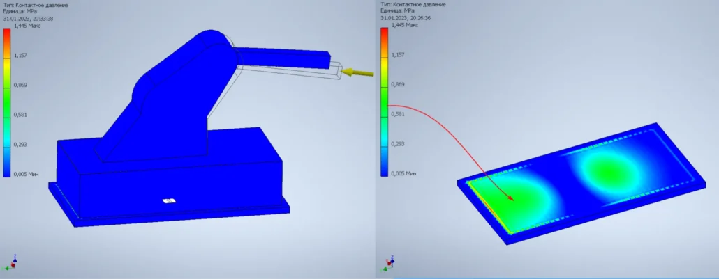
Fig. 4. Distributed pressure on the foundation from the billet pusher of the continuous furnace.
Structural optimization: FEM results analysis allows for optimization of geometry by minimizing weight and cost while maintaining the required strength and stiffness.
Fatigue strength analysis: FEM is used to assess the fatigue strength of elements subjected to cyclic loads, which is especially important for rotating parts of turbines and other dynamically loaded components, particularly high-temperature pipelines.

Fig. 5. Strength calculation of a high-temperature pipeline, isometry.
Stability analysis: FEM allows for determination of the critical load at which a structure loses stability (e.g., column or beam deflection).
Seismic analysis: FEM is used to analyze the behavior of a thermal power station structure during earthquakes, ensuring its seismic stability.
Vibration analysis: FEM allows for the modeling of vibrations in various elements, caused by equipment operation and assessing their impact on the strength and durability of the structure.
Analysis of contact interactions: The finite element method (FEM) gives the possibility of modeling of contact interactions between various structural elements.
Fracture analysis: The finite element method (FEM) can be used to model the process of material damage, which makes it possible to predict potential damage locations.
Particular attention can be given to the use of FEM for calculation of pipelines as a frame structure. We perform strength calculations of pipelines of any complexity and branching for thermal power plants (TPPs), up to supercritical parameters (560°C, 25 MPa) and selection of an optimal support and suspension system according to valid standards in the European Union and the former CIS countries.
It can be confidently stated that the finite element method (FEM) is an indispensable tool for designing thermal power plants, ensuring reliability, safety, and economic efficiency of the project. It enables comprehensive analysis of various aspects of the structure, optimizing its characteristics and minimizing risks.
BIM Modeling in Power Plant Design
After the research is completed, the detailed development of the project begins in all its aspects.
M HEAVY TECHNOLOGY specialists carry out design work in a unified model, which allows the Client to:
– see the progress,
– make decisions and implement changes in real time at any design and construction stage, significantly reducing the time and cost of project execution.
Moreover, this model can also be used after construction is completed for the repair and modernization of the existing facility.
Turnkey Power Plant: Features of the Building Process
I. Pre-design stage (General steps for all parts):
1. Feasibility study (FS): Determining feasibility of building a power plant, selecting the type and capacity, analyzing various location options, and evaluating economic efficiency of the project. At this stage main technical parameters are defined, and a technological scheme is selected.
2. Site selection: such factors such as proximity to fuel sources, availability of infrastructure (transport, water, power lines), environmental restrictions and others are taken into account.
3. Obtaining permit documentation: Coordinating the project with various government authorities, obtaining necessary licenses and permits for construction and operation.
II. Designing individual power plant parts:
A. Boiler part:
1. Selection of a boiler type: Determining the type of boilers (steam, water-heating) depending on the type of fuel and steam parameters.
2. Calculation of steam parameters: Determining steam parameters (pressure, temperature, humidity) according to the requirements of the turbine section.
3. Designing fuel supply system: Selection of the fuel supply system (transportation, storage, fuel supply to the boiler), including fuel cleaning and preparation systems.
4. Designing ash handling system: Selection of the system for removing ash and slag from the boilers.
5. Designing flue gas cleaning system: selection and designing the flue gas cleaning system to reduce emissions of harmful substances.
B. Turbine part:
1. Selection of the turbine type: Determining the type of turbines (steam, gas) based on steam parameters and electricity requirements.
2. Calculation of steam/gas parameters: Determining steam or gas parameters at the inlet and outlet of the turbines.
3. Designing turbine control system: Selection and design of the automatic speed and power control system for turbines.
4. Designing condensation system: Selection and designing steam condensation system to improve turbine efficiency.
C. Electrical substation:
1. Equipment selection: Selection of transformers, circuit breakers and other substation equipment.
2. Designing the chematic circuit diagram: Development of a electrical connection diagram for the substation, ensuring reliable and safe distribution of electricity.
3. Design of the protection and automation system for the substation to ensure its safe and reliable operation.
4. Connection to external networks: Design of the system for connecting the substation to external electrical networks.
D. Gas supply (in cases where the heat source is gas, natural gas, blast furnace gas etc.):
1. Gas source selection: Determining a gas source (pipeline, liquefied gas).
2. Designing a pipeline system: Designing the pipeline system, including gas-control units and safety systems.
3. Designing a gas purification system: Selection and design of a gas purification system to remove impurities.
E. Coal storage facilities (for a coal power plant):
1. Selection of a storage facility type: Determining a warehouse type (open, closed) based on climatic conditions and storage volumes.
2. Calculation of the warehouse capacity: Determining the required warehouse capacity based on the power plant’s coal demand.
3.. Designing a coal transportation system: Selection and design of a coal transportation system from the storage to the boilers.
4. Designing a dust suppression system: Selection and design of a dust suppression system to reduce environmental pollution.
III. Final stages (Common for all parts):
1. Working documentation: Development of detailed working documentation for construction.
2. Construction: Construction of a power plant according to the project documentation.
3. Commissioning works: Conducting commissioning and equipment testing.
4. Commissioning: Putting the power plant into operation after successfully completing all tests.
Each of these stages includes many sub-stages and requires involvement of specialists from our company and related companies.
Development of auxiliary units
Designing water treatment facilities.
The water treatment system and water supply circuit is a critical process responsible for performance and reliability of power generation facilities.
M HEAVY TECHNOLOGY has the best specialists who find solutions and develop unique water supply, wastewater, and drainage treatment circuits for all enterprises, regardless of complexity and the task set.
✔️ Feedwater for boilers, filling the steam turbine plant circuit and compensating steam and heat losses;
The highest requirements are placed on the quality of water used for filling the steam turbine plant circuit and for its make-up during operation. Specialists combine various methods of water treatment for obtaining water of the required quality to enhance equipment operation reliability.
✔️ Equipment cooling
The cooling system for power equipment, operating under high temperatures, is one of the most important elements in the power generation process. Specialists of M HEAVY TECHNOLOGY develop closed-loop water supply systems for thermal, nuclear, combined power plants, as well as for stations of alternative energy generation.
Our experts also carefully develop both water treatment methods for getting the required water quality and design pipeline systems.
✔️ Heat networks make-up.
Development of closed-loop water supply systems with fresh water make-up.
Design of process pipeline systems
Performance and operability of the entire enterprise depends on functioning of process and auxiliary pipeline systems.
Designing pipelines by means of BIM allows to significantly increase accuracy and efficiency of design works, ensuring integration of all aspects of construction into a single digital model. This approach helps minimize errors and costs at the construction stage and facilitates management and maintenance of pipeline systems in the future.
Designing pipelines using BIM allows for a significant increase in the accuracy and efficiency of design work, ensuring the integration of all aspects of construction into a single digital model. This approach helps reduce errors and costs at the construction stage, and also facilitates the management and maintenance of pipeline systems in the future.
M HEAVY TECHNOLOGY experts pay particular attention to high-quality design of pipeline systems, the main of which are:
- Steam pipelines: for steam transportation from boilers to turbines.
- Condensate pipelines: for removing condensate from turbines to condensers or for its reuse in the system.
- Cooling water supply lines: for supplying water to condensers and other cooling systems.
- Feed pipelines: for feed water supply to boilers.
- Fuel pipelines: for transporting fuel (coal or gas) to boilers.
Design of dedusting systems
Preservation of environment and creation of required working conditions in enterprises are the priority areas of M HEAVY TECHNOLOGY.
To minimize harmful emissions and risks associated with dustiness in production our specialists develop individual solutions for cleaning exhaust gases.
Power plant exhaust gas cleaning solutions are influenced by on the following factors:
- Number and capacity of power units;
- The type of fuel used in power units;
– Local environmental regulations and requirements.
Each of these aspects has an impact on initial dustiness of exhaust gases, the number of cleaning stages, a cleaning method and technical parameters of the gas cleaning equipment.
Solving the problem of exhaust gas cleaning at power plants also gives rise to the need of solving another problem – the disposal of captured dust and its treatment.
Process automation
Automation is a key element of modern power plant design. It ensures stable operation, minimizes the human factor and allows for optimization of operational processes, increasing the overall efficiency of the plant.
The process of automation consists of three key stages:
- Planning:
- Analysis of current processes at the enterprise to identify optimization points.
- Concept formation taking into account specific conditions of the equipment operation.
- Selection of equipment and software that comply with international standards and the company’s requirements.
- Implementation:
- Installation of hardware, including sensors, controllers and switching equipment.
- Programming of control systems to ensure accuracy of technological processes.
- Commissioning works with mandatory testing of all operating modes of the system.
- Optimizing:
- Continuous analysis of system operation based on collected data.
- Regular software updates to improve performance.
- Introduction of adaptive control mechanisms for automatic adjustment of parameters depending on external conditions.
Attention to details at every stage ensures maximum benefits from implementation of the automation system and its adaptability to future requirements.
Turnkey Power Plant Services of M HEAVY TECHNOLOGY
M HEAVY TECHNOLOGY develops design documentation for construction of new or modernization of existing thermal and electric generation facilities:
✔️ Сo-generation plants (CHP)
✔️ Thermal power plants (TPP)
✔️ Thermal Power Plant and Turbo Blower Station (TPP-TBS);
✔️ Combined cycle gas turbine (CCGT)
✔️ Gas turbine units (GTU)
✔️ Steam-boiler plants
✔️ Hot-water boiler plants, mini combined heat and power plants based on gas reciprocating units
✔️ Gas Turbine Compressor Sets, diesel-generator units; electrical substations 110-1150 k
It also develops working documentation in all project parts:
- Process;
- Construction;
- Water supply and sewerage;
- Heating and ventilation;
- Electrical;
- Instrumentation and automation;
- Development of design documentation for machine parts, process units and non-standard equipment
- Survey works;
- Feasibility study of projects;
- Audit and assessment of the plant and company.
It also carries out designer supervision and commissioning works.