The efficiency of hot metal smelting in a blast furnace largely depends on the iron content in the ore part of the sinter mix, size, and crushing strength of raw material pieces charged into a blast furnace. Sintering is one of the main methods of preparing raw iron ore materials for blast furnace smelting. Without high-quality sinter, implementing modern energy-saving technologies in blast furnace production and modernizing the metallurgical industry is impossible.
Sinter quality is defined by a constant chemical composition, crushing strength, reducibility, and minimum content of particles with a size class less than 5 mm.
Our company performs the following works:
✔️ Development of construction projects for new sinter plants and revamping existing ones to get required performance, high-quality sinter, and reducing harmful emissions into the atmosphere.
✔️ Support by expert evaluation of design documentation.
✔️ Construction supervision of sinter plant facilities.
Sinter Plant Description
A Sinter plant in a steel plant is the final operation in a series of measures to prepare iron ore for blast furnace smelting. A sinter plant is an enterprise with a complicated technological process for producing the final product – agglomerate or sinter.
Agglomeration is a process of sintering fine ores and concentrates by fuel combustion in a layer of sintered material.
During the sintering process, harmful impurities like sulfur and partially arsenic are removed, and hydrate and carbonate compounds are decomposed.
Using a sinter in a blast-furnace smelting ensures the formation of a burden layer with a suitable gas permeability, a requirement for high-performance furnace operation.
The main components of the iron ore sinter burden are
- fine iron ore and iron ore concentrate (50%) with a particle size of 0-8mm;
- return fine substandard agglomerate from previous sintering (25-30%) 0-5mm;
- fine coke as a solid fuel (4-6%) 0.5-3mm;
- fluxing additives: limestone and dolomite (8-10%) 0-3mm;
- metal-containing additives – waste from metallurgical production (5%) 0-3mm.
The sinter determines the sinter plant’s complex configuration and structure mix clotting technology and includes all necessary processes and equipment to ensure sinter production.
Sinter Plant Process
Sinter plant meaning includes the following processes:
Acceptance and Preparation of Raw Materials
A stationary rotary car dumper is provided for the motor unloading of sinter burden components.
Storage and homogenization of raw materials are carried out in stock heaps of various capacities in a bedding yard.
Sintering ore, concentrate with lime, and iron-containing waste are stored and averaged in two stock heaps: one is formed, and the second is used. The stock heap is created using a rotary single-beam stacker. The iron ore mixture is taken from the stock heap by a reclaimer.
Stacks of fuel and limestone are formed and taken down using a universal rotary stacker/reclaimer.
Averaged iron ore mixture is delivered to the charge bins by belt conveyors.
Sinter ore, iron ore concentrate, return, and metal-containing additives usually have a size suitable for the sintering process and are not sorted or crushed in sinter plants.
Fuel and fluxes are supplied to the sinter plant in pieces, the sizes of which significantly exceed those required for sintering; therefore, they are crushed before being fed to the charge bunkers.
First, the fuel is crushed and then ground to 0.5-3mm. To prevent its over-grinding, a screen is installed, on which the fuel is separated in two fractions of 0.5-3mm and + 3mm. The +3mm fraction is sent to four-roll crushers for grinding, and the combined suitable fraction of 0.5-3mm is sent to the stock house bins.
Limestone sizing means crushing it into a fraction of 0-3 mm, after which it is sent to the stockhouse bins.
Convey weighers are installed on the inter-shop transport conveyors to record raw materials that enter the stock house.
Sinter Mix and Sintering Process Preparation
The batch hopper building is intended to receive prepared materials, return them, and form a sinter burden.
Dosing the burden components onto conveyors is carried out by automatic weighing-type feeders with flow control.
Dosing the burden components onto conveyors is carried out by automatic weighing-type feeders with flow control.
The ready sinter mix is conveyed to the primary mixing unit, where it is thoroughly mixed and moistened in rotating drum mixers at 2/3 of the required quantity. After primary mixing, the sinter mix is transported by a conveyor system to the pelletizing drum for pelletizing and additional moisture to 8-9%. The quality of pelletization is crucial for a normal sintering process. A well-pelletized burden ensures the gas permeability of the layer in the sinter machine. The moistened mix from the pelletizer is loaded into the funnel hopper of the sinter machine by a shuttle distributor, which evenly distributes the burden charged across the width of the funnel hopper. Then, the burden is transferred by a drum feeder to an inclined chute, from which it is placed onto the pallet cars. The position of the gate valve controls the height of the burden layer.
Before loading the sinter burden onto the pallet cars of the sintering machine, a layer of “bed” is first laid – the fraction is (5-16 mm). It prevents the mixture from spilling through the grate, protects the grates from high temperatures, and eliminates mix sticking to the grate.
The burden sintering is carried out on a moving grate of the sintering machine. The air intake required for the oxidation of solid fuel carbon is carried out by exhausters installed on the sinter gas path. Under the grate, a vacuum is created, due to which a flow of hot hearth gases is first sucked into the layer for the burden “ignition,” which means the surface layer is heated approximately to 1200 °C (within 1.5-2.0 minutes). As the sintered burden moves to the discharge part of the sinter machine, the combustion, which begins from the surface of the burden layer, successively passes through the entire thickness of the material and ends at the grate. The solid fuel of the sinter mix burns almost completely. Ore fines in the zone of maximum temperatures (1400-1450°C) are melted and sintered, and then during subsequent crystallization, a porous structure – an agglomeration cake is formed.
Hot sinter crushers are installed after the sintering machines.
The crushed cake (particle size of 150-200mm) comes to the cooling area.
Sinter Cake Processing
For sinter cooling, a cooler is provided. There are two types of coolers: linear and circular.
Sinter cooling to +100ºС uses fans, which blow air through the sinter layer.
When comparing linear and circular coolers and choosing one or the other, consider the following: 1. A linear cooler has a better configuration, and the distance between sintering machines is smaller (if two or more are installed).
- During cooling in a linear cooler, the sinter is raised to a height, i.e., the cooler is also a means of transport.
- Loading and unloading areas are separated in a linear cooler, while in a ring cooler, they are close.
- Cleaning up spills in a linear cooler is easier.
- The linear cooler is less buried, ~ – 3.0 m, and the circular cooler is ~ – 8 m. If the circular cooler is not buried but raised higher, the height of the sintering casing increases.
- A linear cooler has a more powerful drive. Still, if we sum up all capacities of a circular cooler, including the capacity of the sinter conveyors, then the capacities of both coolers are identical.
- The specific quantity of metal per cooler is identical.
- The linear cooler has better maintainability; you can remove and repair any section.
- Their cooling technologies are identical.
A comparison of the two types of coolers (circular and linear) shows that the choice mainly depends on the place available.
The cooled sinter comes to the bar screen, where a +50 mm fraction is separated and crushed in a two-roll gear crusher. Then, the sinter is sorted into fractions:
- 5-50 mm – usable for shipment to consumers;
- 5-16 мм – “bed”;
- 0-5 мм – return fines.
A usable sinter (5-50 mm) is conveyed to the blast furnace shop.
Sinter Machines Gas Cleaning
Bag filters with pulse regeneration are planned to clean the sintering gas of dust.
The residual dust content of agglomeration gases emitted into the atmosphere is 20 mg/m3.
Partly recycling of sinter gases is provided to reduce CO emissions into the atmosphere.
Desulphurization Plant
After bag filters, dust-free gases come to the desulphurization department, where absorption of sulfur oxides (SO2) and partially nitrogen oxides (NOx) takes place in two series-connected desulphurization columns (scrubber and absorber) as a result of their contact with a sprayed limestone suspension.
Spent circulation suspension comes into a tank for gypsum suspension, where it is pumped to filter presses.
Gypsum-containing waste is not toxic or explosive and can be used in cement production and construction.
Sulfur oxide purification efficiency is 98-99%, and nitrogen oxide purification is up to 20%.
Selective purification of sinter gases is provided to reduce the costs of building a desulfurization plant. Sinter gases come to desulfurization from the vacuum chambers of the second half of the sintering machine, where the most significant amount of sulfur oxides is emitted.
Aspiration Air of the Sinter Shop
Dedusting of aspiration air occurs in electric precipitators. Collected dust is pneumatically transported to the primary mixing department or a silo of the burdening department and is returned to the sintering process.
Laboratory Services
The following services are provided:
- Organization of sampling areas for raw materials, burden materials, and sinter.
- Sample conditioning for chemical analysis.
- Chemical laboratory and spectral laboratory.
Equipment
One of the determining factors for creating a modern enterprise is the high-quality process equipment used in production and the availability of industrial experience for process implementation that meets the requirements of modern technology. M HEAVY TECHNOLOGY is very responsible in selecting equipment for its projects.
Therefore, we use the following up-to-date equipment of our strategic partner, DHM GROUP:
- Sintering machines;
- Sintering pallets;
- Mixing drums;
- Single-roll crushers;
- Shuttle-type distributors;
- Scraper devices;
- Two-valve gates, etc.
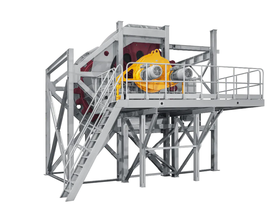
DHM GROUP manufactures conveyor-type sintering machines designed for sintering ores and concentrates with partial removal of harmful additives.
Due to the design of the drive, the charge feeder and seals reduce production costs, increase productivity, save fuel and energy resources, and have other advantages.

The gripping mechanism of the driving sprockets and sintering pallets separates them into round diverters, preventing wear and uneven movement.
- The machine is powered by an electric motor with a unique hinged planetary gearbox.
- The movable unloading part with a load clamp compensates for thermal expansion and eliminates pallet gaps, enhancing durability.
- The sintering pallets’ design allows for up to 700mm of sintering in the upper layer, reducing solid fuel usage and improving quality.
- Idler sprockets separate pallets into round diverters, preventing wear and skewing.
- The cargo seal ensures high tightness.
- Covers for the back and middle sections reduce cool air inflow, dust, and harmful heat emissions.
| SM-75 | SM-190 | SM-200 | SM-250 | |
| Sintering area, m2 | 75 | 192 | 204 | 252 |
| Sintering zone bed width, m | 2,5 | 3 | 4 | 4 |
| Sintering layer thickness, m | 0,3 | 0,5 | 0,5 | 0,5 |
| Sintering pallet movement speed, m/min | 4,5 | 4,5 | 6,0 | 6,0 |
| Capacity, t/h | 82-97 | 209-250 | 224-265 | 277-328 |
Sintering machine drive
The drive can be installed on any refurbished machine with various sintering areas.
- The drive can be installed on any refurbished machine with various sintering areas.
- It is not necessary to coordinate the actions of many gearboxes. Potential overloads and drive stoppage are ruled out.
- Broad control over the sintering belt’s speed.
- Special design eliminates the requirement for extensive, heavily loaded connections.
- Misalignment of the drive drum shafts and the gearbox’s output shaft is excluded.
Single-roll crusher
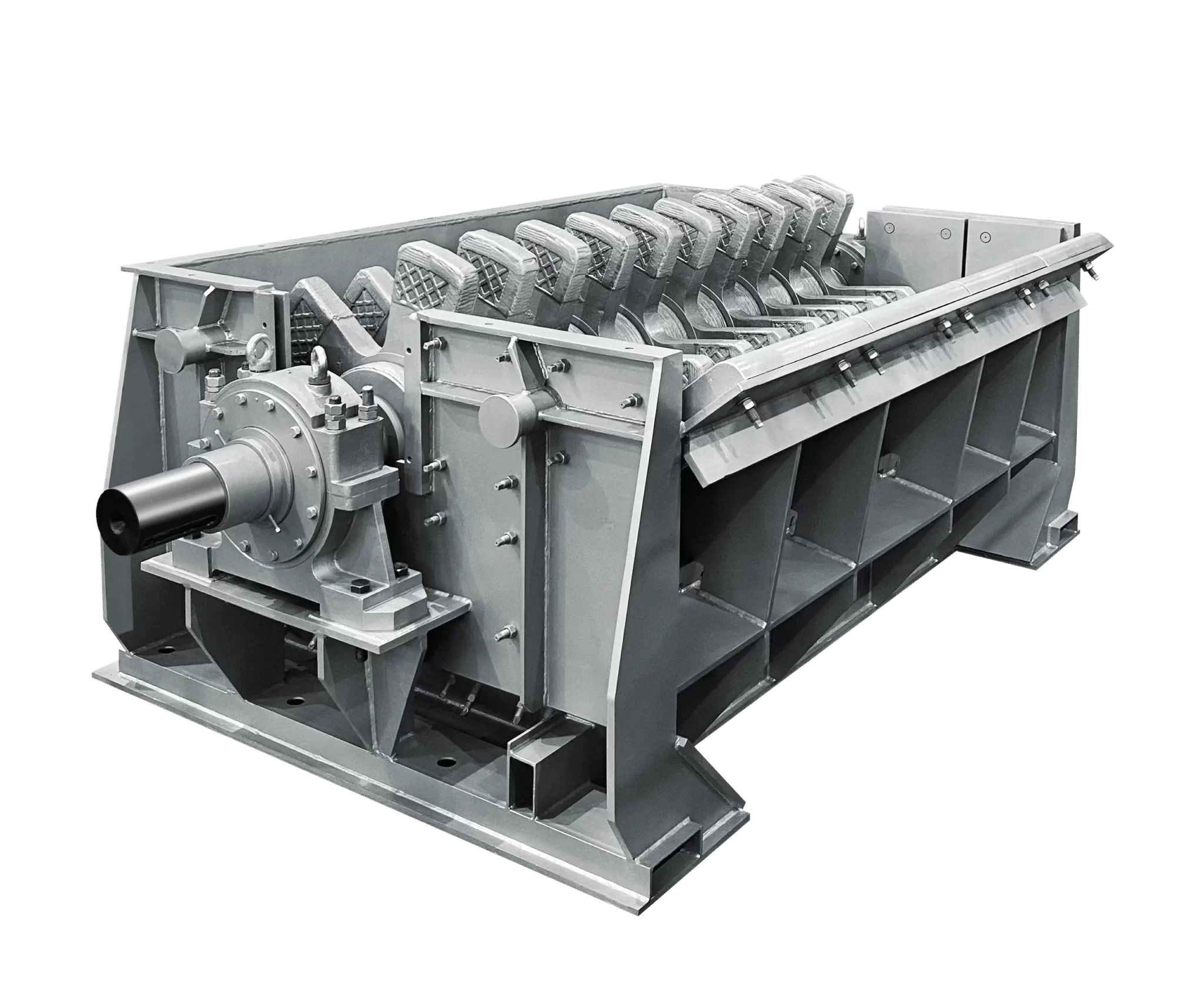
- High-alloy steel sprockets with a strong face are resistant to heat.
- The fire grate can be rolled out, which significantly facilitates maintenance.
- The frame is lined with interchangeable plates on the inside.
Loading part
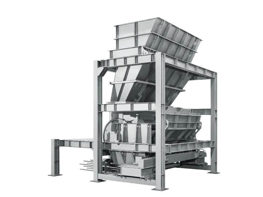
- Charge is kept from hanging in hopper corners by pneumatic caving.
- Weighing sensor vibration and disturbance are prevented by directional impact.
- A gas permeability device guarantees efficient gas penetration and consistent sintering by releasing charge.
- The feeder drum is equipped with stainless steel lining that is replaceable without drum dismantling.
Sintering pallet cars
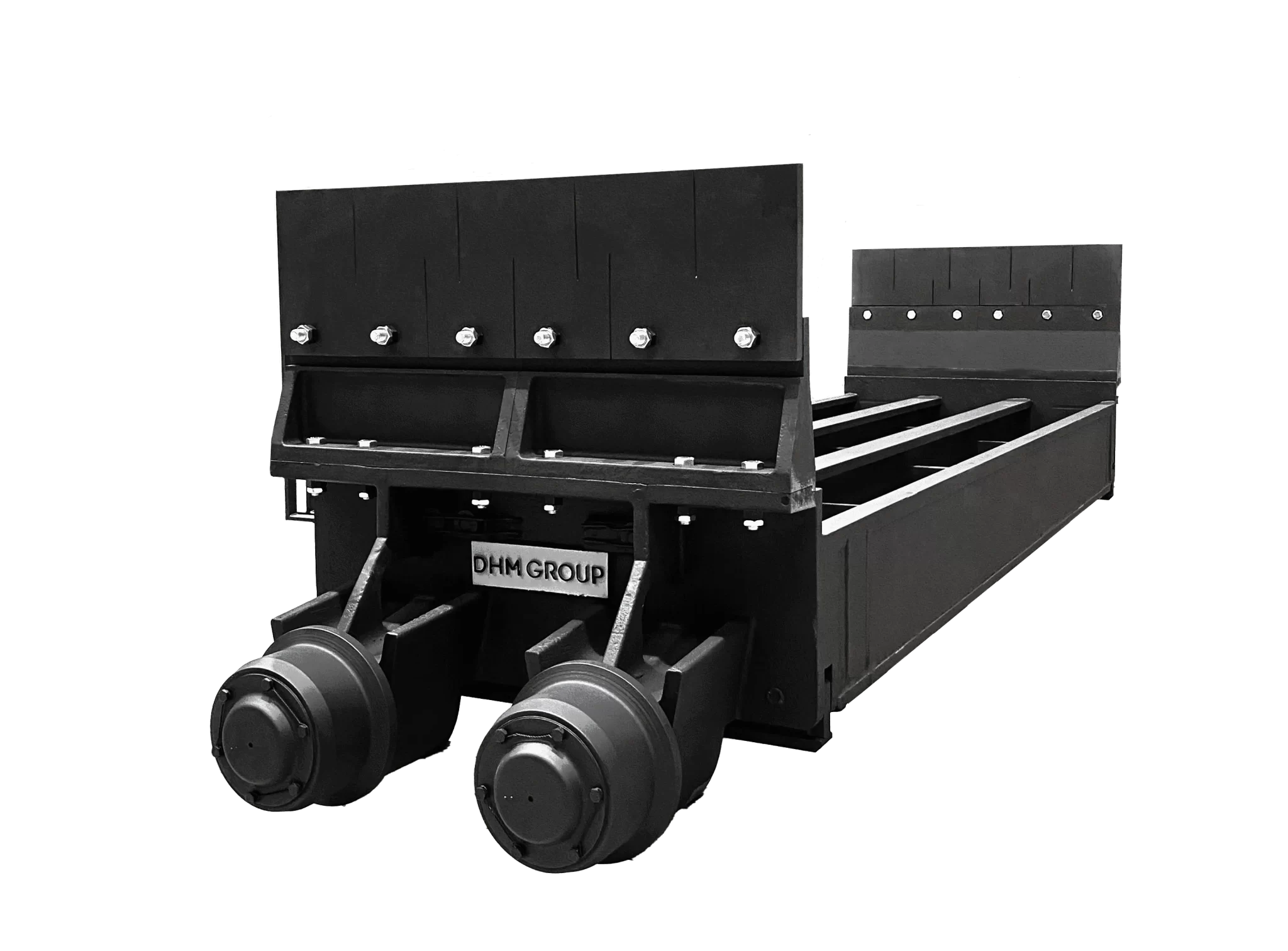
- Because the unique steel used in constructing these pallet cars increases strength at high temperatures, the overall weight is reduced by 30%.
- The sealed bearings in the running rollers are lubricated with high-temperature greases no more frequently than once every four to six months.
- The sintering vehicles have a sturdy cargo seal, which raises the vacuum beneath the grate and, in turn, the sintering machines’ output.
Automation
A modern information system for extensive industrial enterprise automation looks like a pyramid, at the base of which automated process control systems (APCS) are located in the middle part of MES systems and the top part of ERP systems. The process control system of a sinter plant is an integral part of the enterprise automation system. It is designed for technological process control of the sinter plant and its optimization for producing sinter with minimum participation of operators.
Sinter plant APCS includes the following sub-systems:
- Handling control system: burden material supply, coke fines, and limestone supply from receiving bins of brought-in materials;
- Bedding plant bins and sinter mix dosing area;
- Maintaining a preset burden material level in intermediate bins above sintering machines;
- Material mixing and feeding area into intermediate bins of the sinter plant building;
- Sintering area;
- Sinter supply to the loading unit;
- Filter section of the sintering and cooling area;
The process control system of the sinter plant is a two-level system with a distributed structure.
- At the first (lower) level, sensors, controllers, and actuators are connected by various field networks. (Level L0-L1);
- The second (upper) level consists of visualization servers, operator and engineering stations, database storage stations, etc. (Level L2).
1. Control functions:
- Starting and braking mechanisms (valves, flue-gas fans, drum cart conveyors, vibrators, lock feeders, belt-conveyor weighers, compressors, valve trims);
- System of process interlocks;
- Protection of machines and mechanisms when emergency sensors are triggered;
- Warning alarms when instrumentation sensors are triggered;
- Level 0 protection (self-start protection);
- Generation of pre-start sound and light alarms.
2. Functions of process parameters monitoring and control:
- Temperature control in the hearth;
- Maintenance of gas/air ratio;
- Flue gas temperature control in the hearth panels;
- Pressure control in the shelters of sinter machines;
- Maintaining vacuum after cyclones of sinter machines;
- Water and steam flow control in the pelletizing drum;
- Control of utility parameters (temperature, pressure, level, consumption of natural gas, air, water, steam);
- Level control of the sintering mix, limestone, and coke in bedding plant bunkers, in sintering mix feed hoppers and the bed of the sinter buildings, and in loading unit bins;
- Flue gas control;
- Control of CO concentration in various sinter plant areas;
- CO control in vacuum chambers;
- Control of sintering and cooling zones.
3. Software functions:
- LEL control on CO (up to 20%) before the electrostatic precipitator.
- Receive, generate, and transmit data from sensors and field-level devices;
- Obtain information, mathematical processing, generation, and data transmission from actuators (including frequency converters and soft starters).
4. General tasks when creating an automated process control system:
- Reduction of fuel consumption during sinter production through the use of control systems;
- Stabilization of product quality;
- Achieving stable performance indicators of sintering machines, eliminating fluctuations in control actions, eliminating emergencies;
- Identical sinter plant operating schedules for all shifts;
- Emission abatement.
Ecology Impact
Sinter plant technology is the largest source of environmental pollution of all technological stages in ferrous metallurgy. It accounts for up to ~70% of all toxic emissions into the atmosphere from a metallurgical enterprise. Flue gases from the sintering process contain dust, carbon monoxide, sulfur, and nitrogen oxides. In addition to iron oxides, sintering dust contains significant amounts of fluorine, chlorine, arsenic, chromium oxide, zinc, manganese, copper, mercury, lead, and other heavy metals.
Modern methods of cleaning sinter gases of toxic ingredients are technically complicated and very expensive due to vast volumes of waste gases. Their implementation requires capital investments of 25-30% of the cost of the main technological structures and no less than that of operation costs. In addition, most of the old sinter plants need the necessary conditions for the placement and construction of modern gas treatment complexes, which is why the main technological structures need to be reconstructed.
In the current conditions, the only acceptable direction for solving environmental problems is the modernization of existing gas cleaning systems of sinter machines with the implementation of technical solutions that will radically improve their operation efficiency.
M HEAVY TECHNOLOGY has developed and successfully implemented a set of devices for the modernization of existing process gas removal and purification systems of sintering machines, which fully consider production specifics and make it possible to achieve the required result utilizing the existing equipment with minimal costs for its modernization.
The developed devices, which radically improve dust collection in existing inertial dust cleaning units, use a new principle based on long-wave vortex flow with a rational mutual arrangement of vortex and dust deposition planes. For the first time, it was possible to coordinate the action of two main physical forces – the inertia of dust particles and the dynamics of the gas flow, which made it possible to achieve a sharp increase in efficiency.
Read more in our flue gas cleaning guide.
Benefits of Sinter Plants Modernization
Sinter plants built more than 40-70 years ago have high wear and tear and are morally and physically outdated. They do not contain equipment for high-quality averaging of initial components of the sinter mix. Therefore, there are significant fluctuations in the sinter’s iron content, basicity, and fractional composition. In addition, there is no effective equipment for dosing raw materials, mixing and pelletizing the sinter mix, cooling, crushing, and especially sinter screening.
It has a direct negative impact on the three most important parameters:
- production rate of sintering machines,
- ready sinter quality,
- blast furnace operation results.
The main work at domestic sinter plants aims to ensure production with the required amount of sinter, for which maintenance repairs of equipment are performed without significant reconstruction works.
Our technologists will help you modernize your enterprise, offer solutions to improve technology, and upgrade the sinter plant process equipment. As a result, you will get:
Increased productivity;
Improved sinter quality;
Automated operation control for increased productivity;
Cleaner, safer environment with reduced emissions and radiation;
Reduced solid fuel consumption for savings costs and resources.
Why to Choose Sinter Plant Solutions of M HEAVY TECHNOLOGY
Experience and Qualifications of M HEAVY TECHNOLOGY Specialists
Our specialists have the necessary experience and knowledge to implement projects for constructing new sinter plants and modernizing and reconstructing the existing ones. In our projects, we always take an active, creative approach and offer customers the most competitive solutions for their enterprises.
Application of Modern Technologies
The projects incorporate the latest achievements of domestic and foreign sinter production, aimed at obtaining high-quality sinter and meeting the requirements for the protection of air and water basins.
Project Support at All Stages Until Optimal Results Are Achieved
Our experts support your project by drawing up technical specifications that consider all features of a specific sinter plant to achieve the best result.
Application of Modern Design Technologies
A modern software package with BIM technology (3D information modeling) is used when developing design and working documentation for capital construction projects. A three-dimensional model of the future object created through this technology clearly shows the location of the process equipment, pipes, and utility lines. It lets you have an honest idea of the future object already at the design stage and minimizes design errors.
M HEAVY TECHNOLOGY Sinter Plant Technology Engineers


Case Studies
“MODERNIZATION OF SYSTEMS FOR REMOVAL AND PURIFICATION OF PROCESS GASES FROM SINTERING MACHINES” AT PJSC “KAMET-STEEL,” Kamenskoye.
In the conditions of the sinter plant of KAMET-STEEL, the operation of gas cleaning facilities needed to be more efficient. The residual dust content of sinter gases emissions into the atmosphere was ~400-500 mg/nm3, and in case of violations of the technological and gas cleaning modes, it increased to 1-1.5 g/nm3. It created serious problems for the region’s environment and the regular operation of the leading process equipment.
Our company was tasked to reduce dust emissions into the atmosphere from all sinter plant sources to the level of ~ 100 mg/nm³. The need to solve this problem was obvious and dictated by the necessity to comply with legislation and obligations assumed by the enterprise. Besides, our solution was economically beneficial for the enterprise, as it significantly improved technical and economic production indicators by increasing the service life of equipment, reducing irretrievable losses of raw materials and fuel, and using the heat of sinter gases.
As a result of detailed examinations of existing gas exhaust tracts of sintering machines, gas flows, and gas cleaning facilities with an assessment of the operating efficiency of their main functional elements, significant reserve opportunities for their improvement were identified, and technical solutions for modernizing these systems were found.
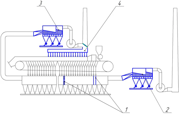
The general flow chart of the comprehensive modernization of the existing systems for the removal and purification of sinter gases is shown in Fig. 1.
As part of the presented complex, it was proposed to modernize the following main elements of gas exhaust tracts of sintering machines:
- gas collectors for sintering zones with the installation of gas-dynamic diaphragms and dust-precipitating pipes;
- battery cyclones for sintering zones with their conversion into two-stage dust-trapping units;
- battery cyclones of sinter cooling zones with their conversion into two-stage dust-trapping units;
- hot air release lines from sinter cooling zones with its return into the process (recirculation).
- Modernization of gas collectors of sintering zones with the installation of dust-precipitating pipes and gas-dynamic diaphragms.
- Modernization of battery cyclones in sintering zones.
- Modernization of battery cyclones in cooling zones.
- Recirculating system for hot gases from the cooling zones of sintering machines and their return into the sintering process.
The above solutions allowed us to solve all the tasks set.
Besides design technologists, the company has specialists who perform mathematical modeling of sinter process parameters.
Mathematical modeling of the sinter process makes finding optimal solutions when planning and managing production possible.
The works performed:
DNIPRO IRON AND STEEL WORKS (PJSC “DMK”). Working documentation of the facility Sinter shop No. 2.
Capital overhaul of sinter machine №7 with reconstruction of air supply to the sinter cooling zone and construction of a sinter machine shelter. Mathematical modeling of heat/mass transfer processes in the sinter machine shelter with dimensioning of the main structure elements of the shelter when using recirculation air of the cooling zone.
As part of this work, a computer modeling of recirculation gas flows through the sinter mix layer and the shelter was performed. The results of this calculation were used to determine and optimize the size and profile of the shelter and the possibility of coupled operation of the existing draft equipment using a recirculation scheme. As a result of a series of optimization calculations, the shelter’s optimal shape and location concerning the sinter machine’s hearth and the operational characteristics of the reconstructed sinter machine were determined.
Related Products & Solutions
For rational use of raw materials and eliminating waste, it was planned to return various iron-containing waste from metallurgical production (scale from rolling shops, top dust from blast furnaces, captured in cyclones or dry dust electrostatic precipitators, dehydrated and dried sludge from wet-type gas cleaning plant) into the process.
To eliminate the negative impact on the sintering process and sinter quality, iron-containing waste had to be treated, and its content in the sinter mix had not to exceed 5%.
In addition to ore raw materials, sinter returns were added to sinter mix (up to 30%). The returns improved the gas permeability of the mix, loosening it and playing the role of pelletizing centers for lumps during mixing and pelletizing.
During the sintering process, secondary energy resources are formed in the form of gases from sinter machines with a temperature of 120-160 ºС and hot air with a temperature of up to 350ºС coming out from sinter coolers.
To use low-grade heat of sinter gases, their partial recirculation was provided. Purified sinter gases after the exhauster were fed by a flue gas fan under the casing of the sintering machine. The approximate degree of recirculation was 22-25%.
Gas recirculation to the sinter machine reduced the amount of dust and CO emissions by 22-25% and decreased solid fuel consumption by 2-3 kg/t.
Hot air from the shelters of the first two sections of the sinter cooler was used in one or a combination of several ways:
- With the generation of steam for the needs of the enterprise;
- With the production of hot water for heat supply to the plant facilities;
- With air supply for combustion of fuel into the ignition furnace and the sinter mix layer behind the hearth of the sinter machine;
- With sinter mix heating
- With hot air supplied to the flue gas recirculation system. For this purpose, air with a temperature of ~350ºС and recirculation was used for heat treatment of the sintered mix layer after the ignition furnace.
Using the heat of hot air exhausted from the sinter cooler also saved fuel for the sintering process and reduced the initial concentration of harmful gaseous substances in sinter gases.